
Understanding thermostat wiring is crucial for both homeowners and HVAC technicians. Properly connecting the wires ensures the thermostat functions correctly, accurately controlling the heating and cooling system. Incorrect wiring can lead to system malfunctions, inefficiencies, and even damage to the equipment. This guide provides a visual aid for interpreting common thermostat wiring diagrams, focusing on two popular models: the Honeywell VisionPRO 8000 RedLINK and the Heatmiser DS1.
Honeywell Wifi Thermostat Wiring Diagram
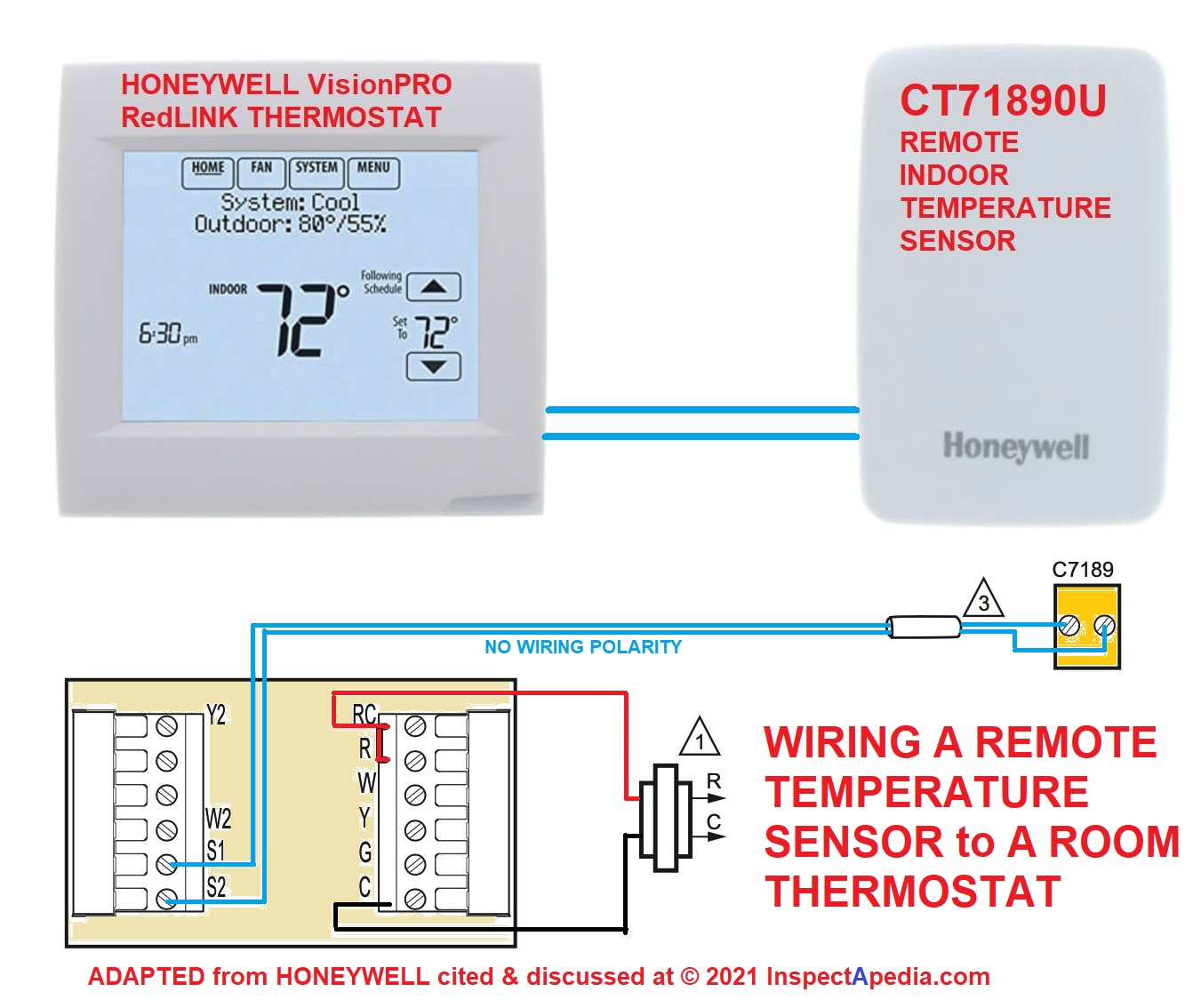
The Honeywell VisionPRO 8000 RedLINK is a sophisticated smart thermostat that offers remote control capabilities via Wi-Fi. Its wiring diagram typically includes terminals labeled R, Rc, Rh, W, Y, G, C, and often terminals for auxiliary heating and cooling stages (W2, Y2). The R terminal is for the 24VAC power supply, with Rc and Rh often jumpered together for single-transformer systems. The W terminal controls the heating system, Y controls the cooling system, and G controls the fan. The C terminal, also known as the common wire, provides a constant power source for the thermostat, which is essential for many smart thermostats to function correctly, especially those requiring Wi-Fi connectivity. When installing this thermostat, it's critical to identify each wire accurately and connect it to the corresponding terminal. The RedLINK system also incorporates wireless communication with other devices, so understanding the specific wiring requirements for any RedLINK accessories is also important. Careful attention to the wiring diagram will ensure seamless integration and optimal performance of the Honeywell VisionPRO 8000 RedLINK thermostat.
Heatmiser Ds1 Wiring Diagram

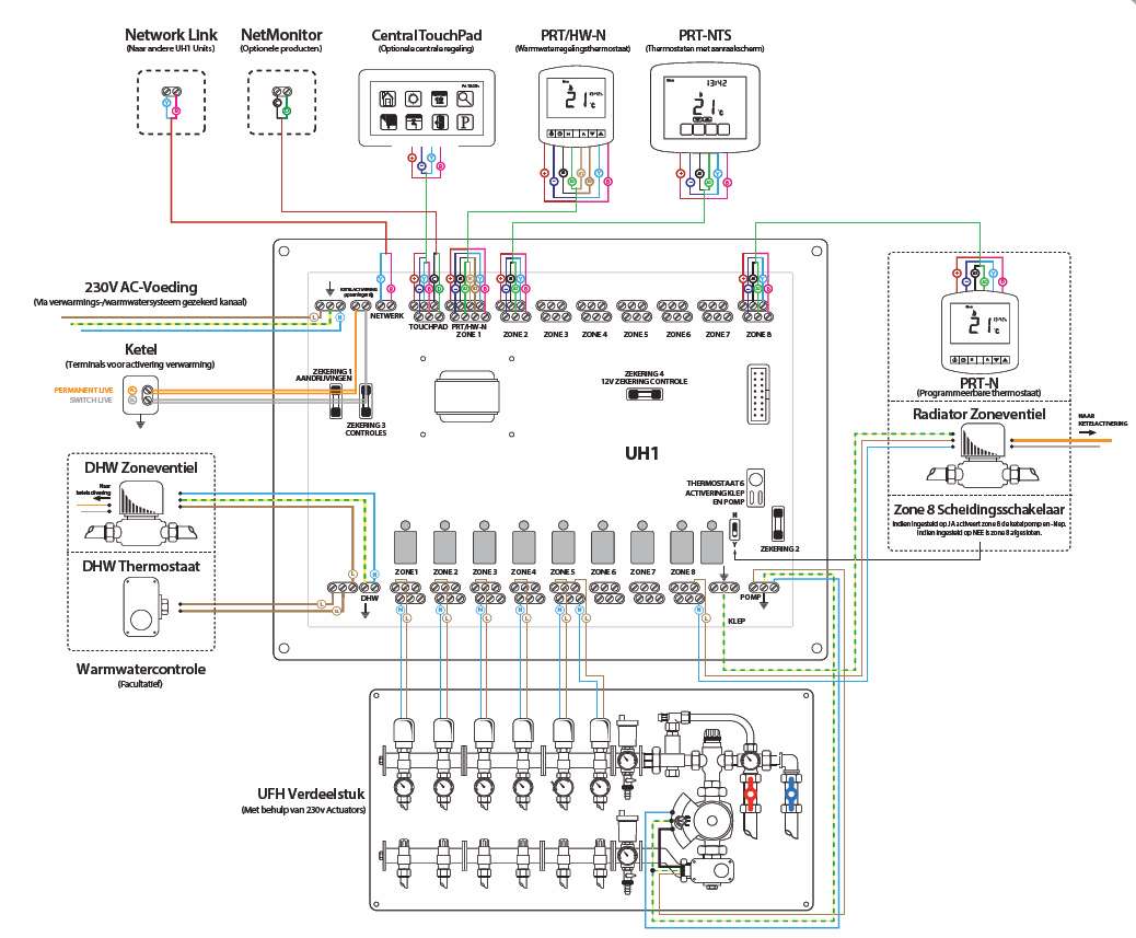
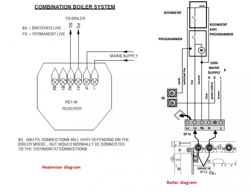
The Heatmiser DS1 is a digital thermostat often used for underfloor heating systems. Its wiring diagram typically shows connections for power (live and neutral), the heating output, and sometimes sensor inputs for floor or air temperature monitoring. The wiring for the DS1 is usually simpler than that of a more feature-rich thermostat like the Honeywell VisionPRO 8000 RedLINK, as it often focuses solely on controlling a single heating zone. The live and neutral wires provide power to the thermostat, while the heating output is connected to the heating element or valve. The sensor input allows the thermostat to accurately monitor the temperature of the floor or air, ensuring consistent and comfortable heating. Incorrect wiring of the Heatmiser DS1 can result in the underfloor heating system not functioning correctly or potentially damaging the thermostat or heating element. Therefore, it is essential to carefully follow the wiring diagram and double-check all connections before powering on the system. Many DS1 models also include settings for adjusting the temperature range and heating schedule, which can be configured after the wiring is complete.
If you are searching about Heatmiser Neo Wiring Diagram you've came to the right page. We have 25 Images about Heatmiser Neo Wiring Diagram like Heatmiser Wifi Thermostat Wiring Diagram - Wiring Diagram, Heatmiser Underfloor Heating Thermostat Wiring Diagram - Circuit Diagram and also Heatmiser Underfloor Heating Wiring Diagram. Read more:
Heatmiser Neo Wiring Diagram
 diagramweb.net
 wiring heatmiser neo ds1 ufh heating diagrams easy
Heatmiser Underfloor Heating Thermostat Wiring Diagram - Circuit Diagram
 www.circuitdiagram.co
 Heatmiser Underfloor Heating Thermostat Wiring Diagram - Circuit Diagram
 www.circuitdiagram.co
 How To Wire A Honeywell Baseboard Thermostat: A Comprehensive Wiring
 autoctrls.com
 Heatmiser Neo Wiring Diagram
 diagramweb.net
 heatmiser conventional radiator caters heating underfloor
Goodman Heat Pump Thermostat Wiring Diagram
 wiringdbxiraumo.z21.web.core.windows.net
 Heatmiser Underfloor Heating Wiring Diagram - Circuit Diagram
 www.circuitdiagram.co
 Heatmiser Underfloor Heating Wiring Diagram
 www.circuitdiagram.co
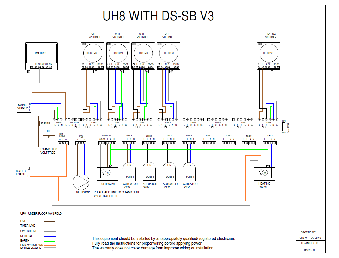
 Heatmiser Uh8 Underfloor Heating Wiring Diagram - Circuit Diagram
 www.circuitdiagram.co
 Heatmiser Underfloor Heating Wiring Diagram - Circuit Diagram
 www.circuitdiagram.co
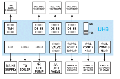
 Heatmiser Uh3 Wiring Diagram
 www.chanish.org
 uh3 wiring heatmiser centre wired
Heatmiser Neo Wiring Diagram
 diagramweb.net
 wiring heatmiser thermostat stat pdf
Heatmiser Underfloor Heating Thermostat Wiring Diagram » Circuit Diagram
 www.circuitdiagram.co
 Heatmiser Uh3 Wiring Diagram
 www.chanish.org
 wiring heating heatmiser uh3
How To Properly Wire Your Nest Thermostat: A 4-Wire Diagram Guide
 resolutionsforyou.com
 Heatmiser Wiring Diagram - Wiring Diagram Pictures
 schematron.org
 Honeywell Wifi Thermostat Wiring Diagram
 animalia-life.club
 Heatmiser Ds1 Wiring Diagram
wiringall.com wiring heating manifold diagram underfloor heatmiser ds1 heat centre floor ufh radiant plumbing pex air luxury pump actuators system valve
Heatmiser Underfloor Heating Wiring Diagram - Circuit Diagram
 www.circuitdiagram.co
 Heatmiser Neo Wiring Diagram
 diagramweb.net
 wiring heatmiser neo thermostat ds1 tado hexus uh8 centres
Heatmiser Wiring Diagram - Wiring Diagram Pictures
 schematron.org
 worcester heatmiser combi receiver greenstar diynot 30si thermostat lcd override timer setting switching
UH8 Wiring Diagram | Heatmiser
 www.heatmiser.com
 Honeywell Wifi Thermostat Wiring Diagram
animalia-life.club Danfoss 2 Port Wiring » Diagram Board
 www.diagramboard.com
 Heatmiser Wifi Thermostat Wiring Diagram - Wiring Diagram
 wiringdiagram.2bitboer.com
 Wiring heating heatmiser uh3. Heatmiser neo wiring diagram. Uh8 wiring diagram